Solar Sail Deployment Mechanism
A boom deployer for the MIRAS solar sail mission as a conceptual design competition. One spur gear turns four spools, and spring-loaded arms keep each carbon-fibre coil tight as it pays out.
RoleConcept Design
- 3rd place · CAST design challenge, MAHE 2025
- Four CFRP tape-spring booms
- One drive, four spools
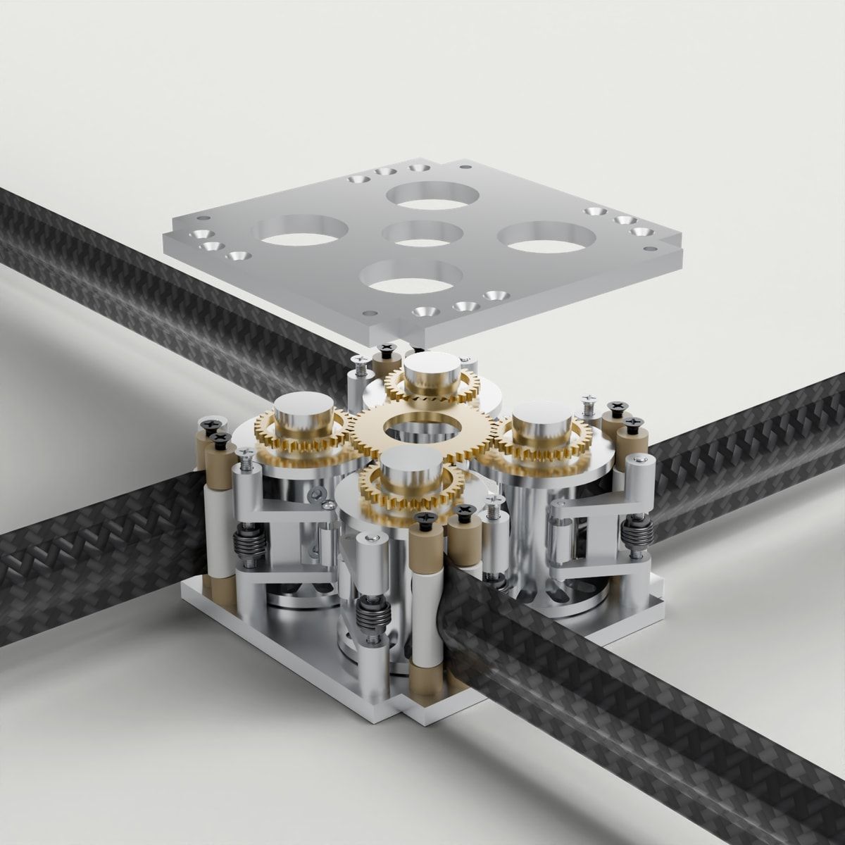
INSIDE THE CUBESAT
Four spools, one drive.

Packed for launch.
Four coiled CFRP booms and a shared drive, carried inside a 3U CubeSat.
- 1Top plateAluminium
- 2Bottom plateAluminium
- 3FastenersStainless and alloy steel
- 1SpindleAluminium
- 2Top flangeAluminium
- 3Bottom flangeAluminium
- 4Tape-spring boomsCFRP
- 1Drive gearsSpur drive
- 1Tensioner armsAluminium
- 2Torsion springsSteel
- 3Boom guide rollersPEEK

Structure
Two aluminium plates hold every spindle, arm and guide. Screws fix the boom roots, guides and tensioners.
- Top plateAluminium
- Bottom plateAluminium
- FastenersStainless and alloy steel
Four spools
Each boom root is bolted to its own spindle. Two flanges keep the coiled CFRP tape seated as it turns.
- SpindleAluminium
- Top flangeAluminium
- Bottom flangeAluminium
- Tape-spring boomsCFRP
One drive
A central 48-tooth gear turns four 32-tooth spool gears, so all four booms leave at the same rate.
- Drive gearsSpur drive
Tension control
Torsion springs press pivoted arms on the outer layer of each coil. Rollers guide the tape out.
- Tensioner armsAluminium
- Torsion springsSteel
- Boom guide rollersPEEK
Watch the booms deploy.

One drive. Four spools.
A central spur gear turns four independent spools together, keeping the boom release coordinated.
- Boom out
- 0.00 m
- Coil
- Ø34.7 mm
- Spool turns
- 0.0
DESIGNED FOR MIRAS
A concept study with Barani Ilango B.
Third place in the CAST design challenge at MAHE, 2025.
CAD concept
No hardware testing
Next
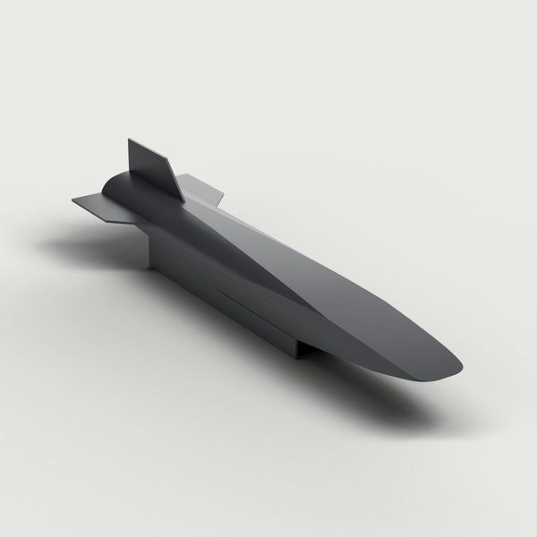
Hybrid reaction-jet and aerodynamic control of an air-breathing hypersonic vehicle
Blending aerodynamic controls and reaction jets to share the work of manoeuvring a hypersonic vehicle.
RoleFlight dynamics research2026