Solid Propellant Research
A reusable threaded-closure motor hardware built as a platform for novel propellant research. Nitrate based propellants that calculate 40% to 75% above KNSB in specific impulse were made.
RolePropulsion Lead
- +40% to +75% Isp over KNSB, calculated
- Ø73 × 220 mm aluminium casing
- Proof-tested at 1.5 × MEOP
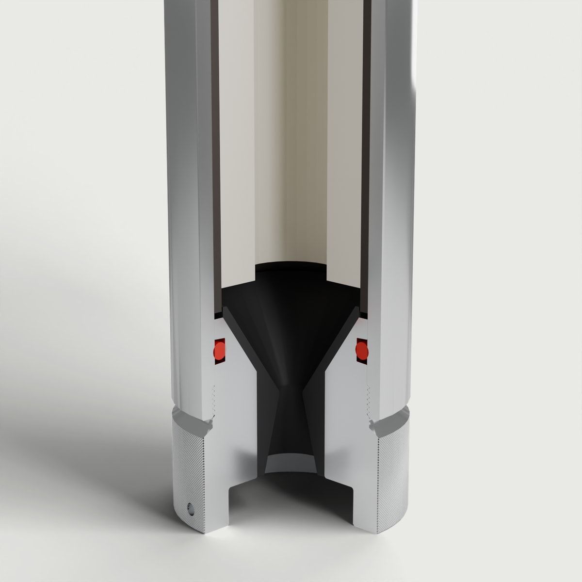
Inside the research motor
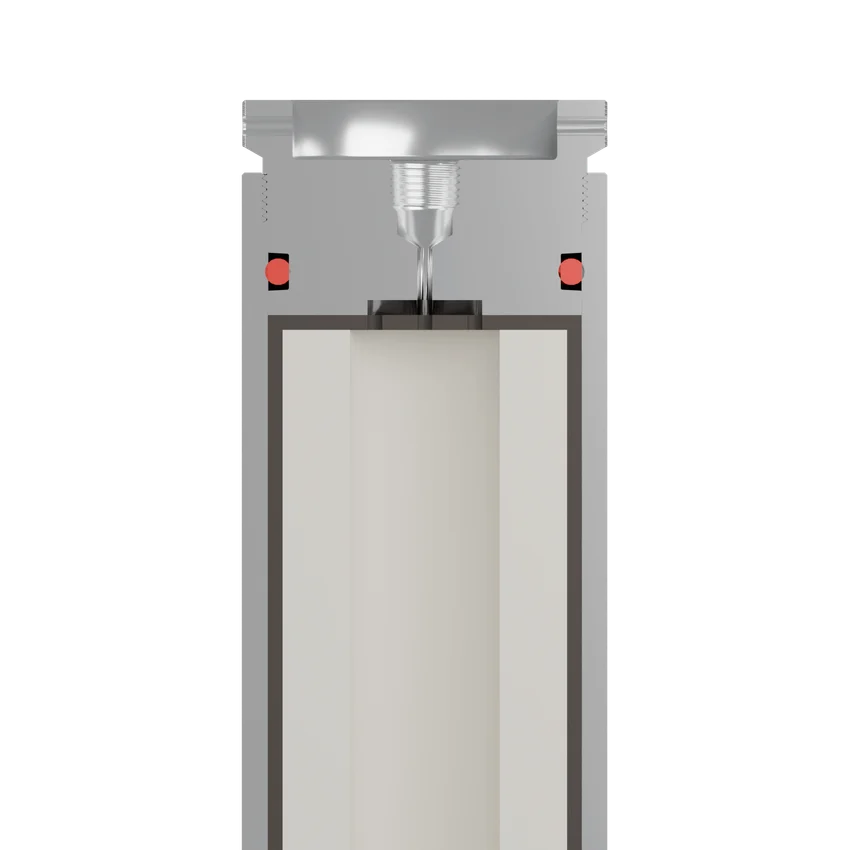
Forward closure
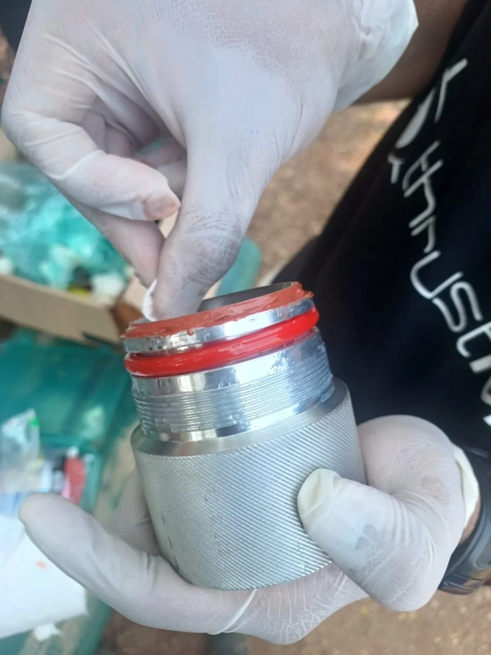
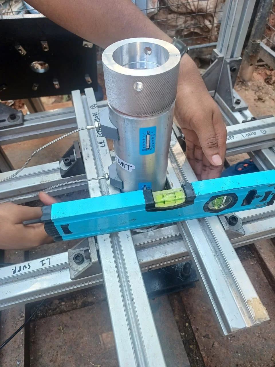
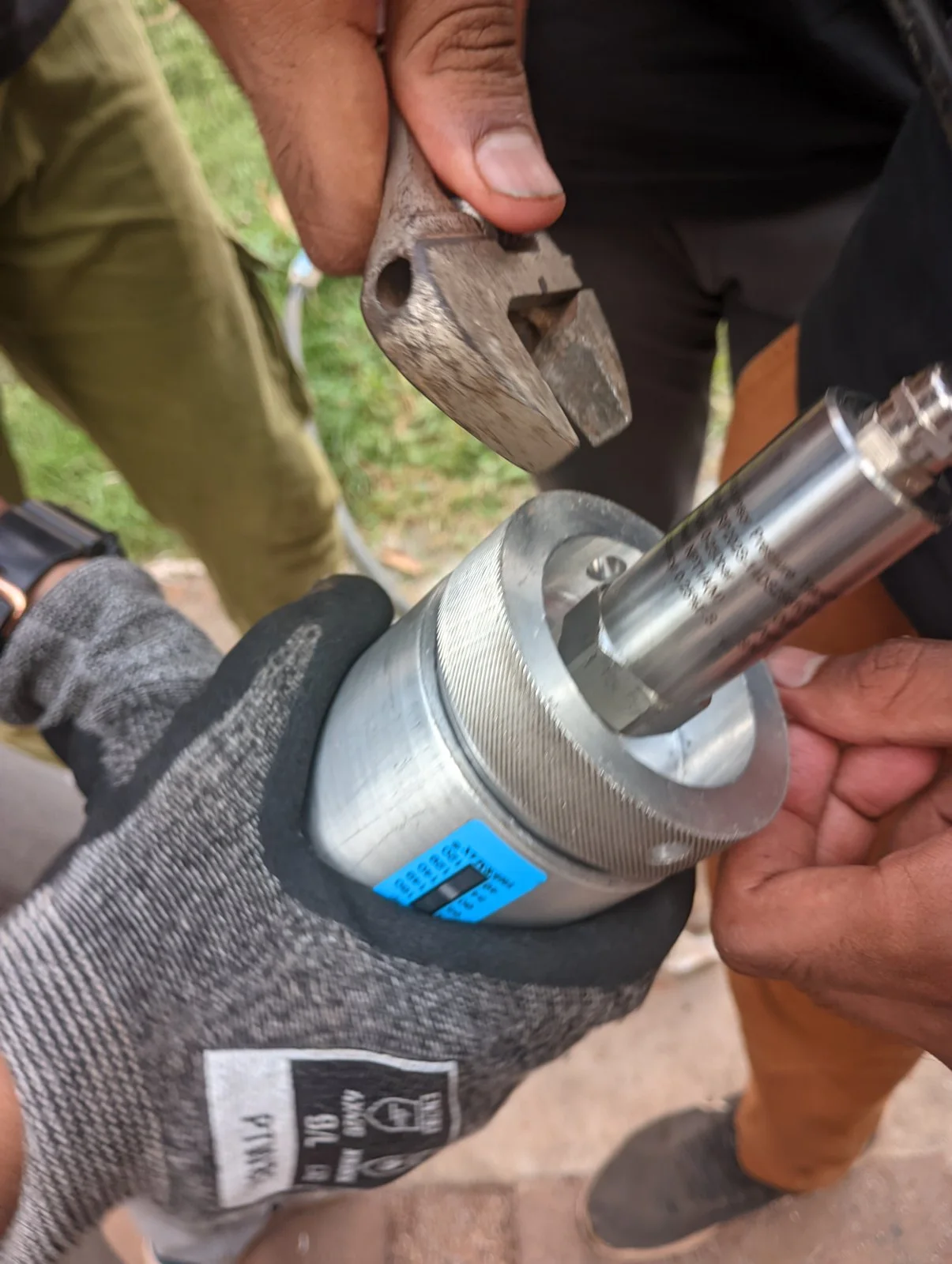
A knurled aluminium closure that threads straight into the casing, so the motor can be taken apart for the next propellant. A port through it takes the chamber pressure transducer, and a carbon-fibre disc shields its face from the flame.
- Thread
- Metric, threaded in
- Engagement
- 10 mm
- Port
- Pressure transducer
Propellant grain
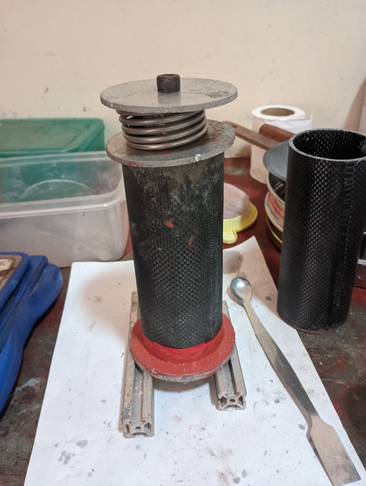
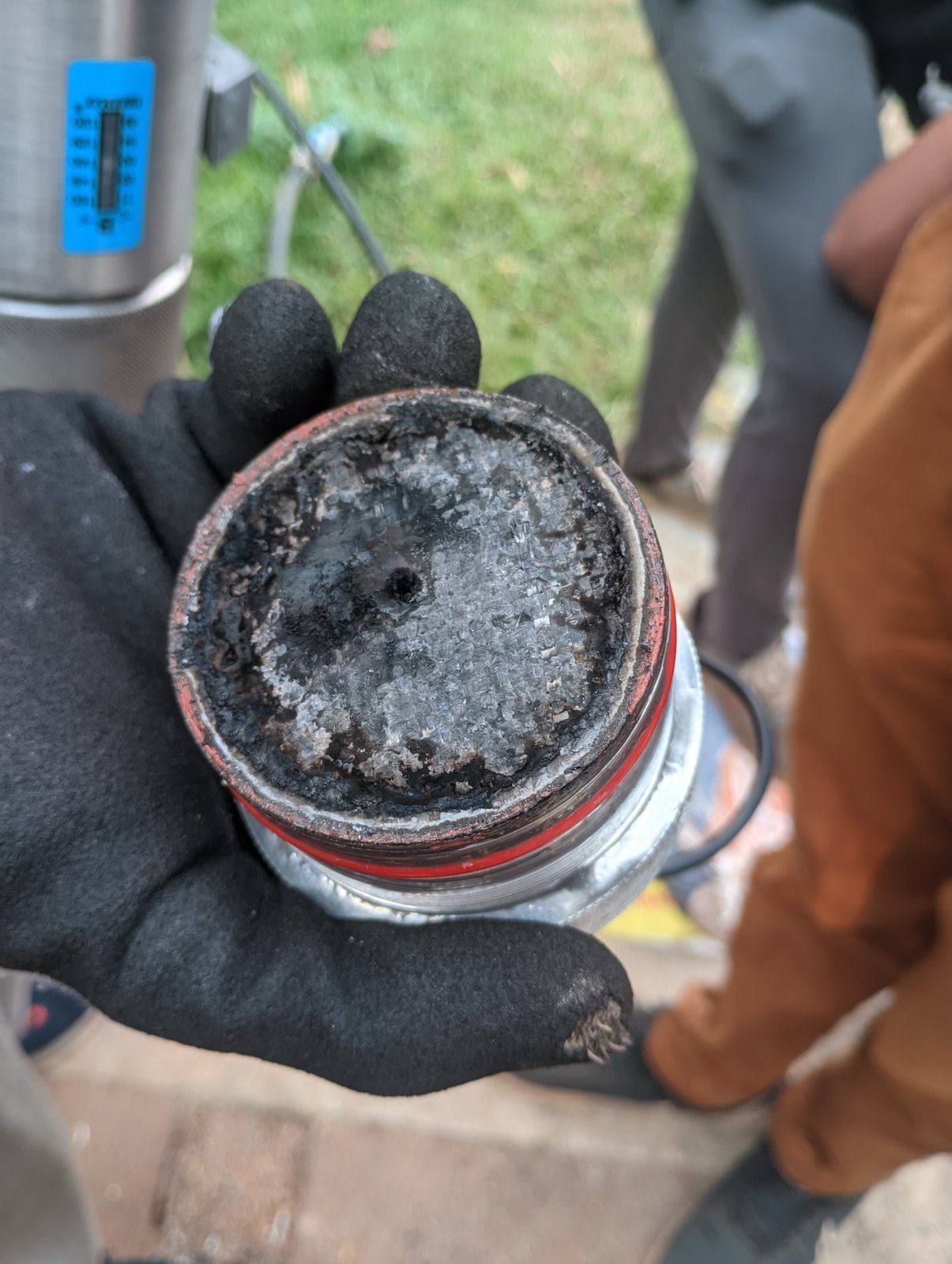
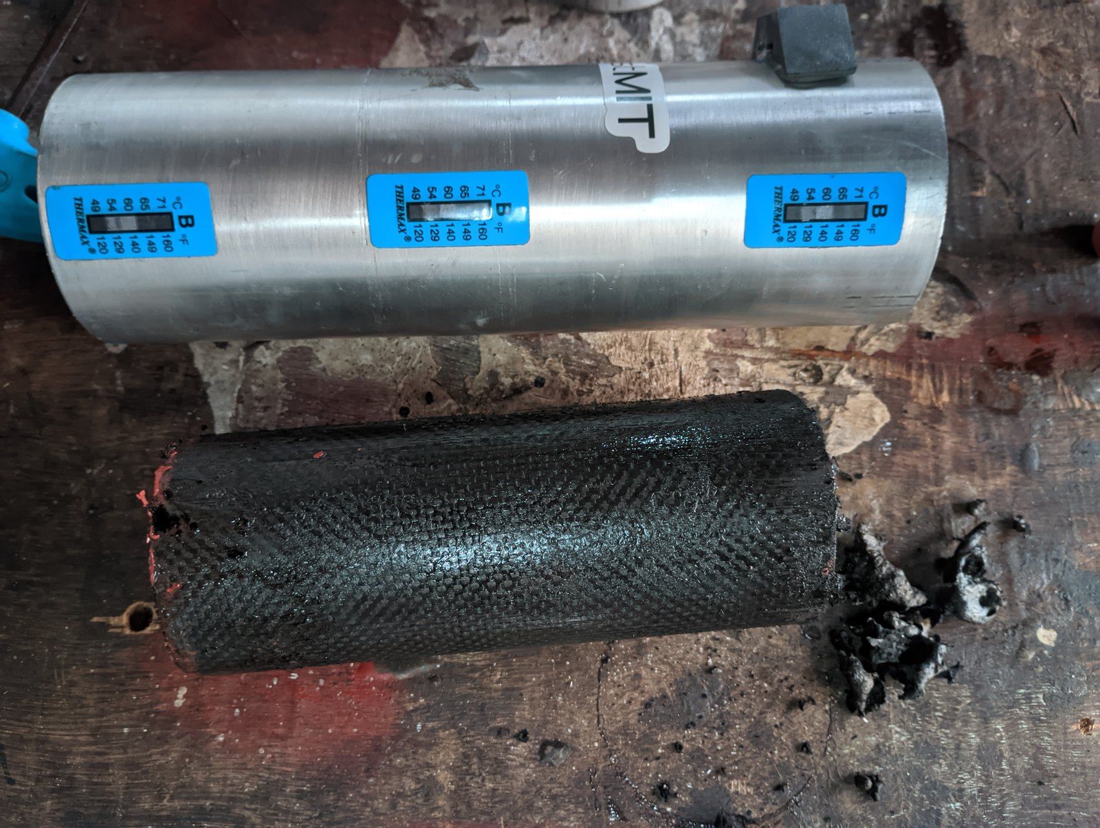
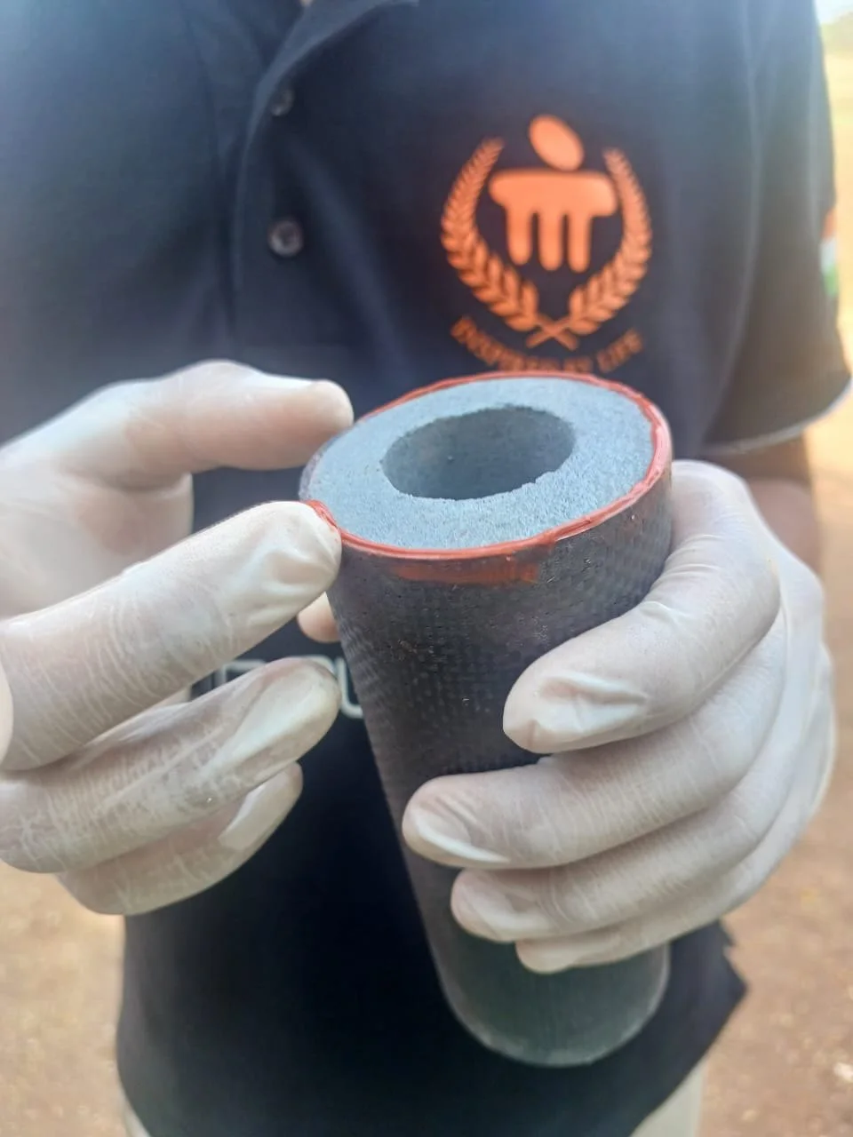
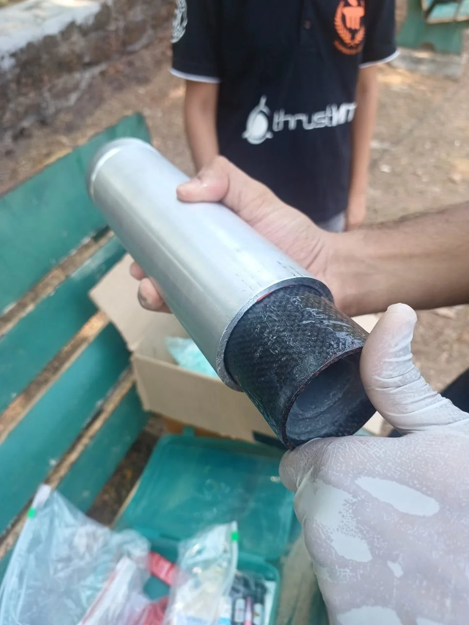
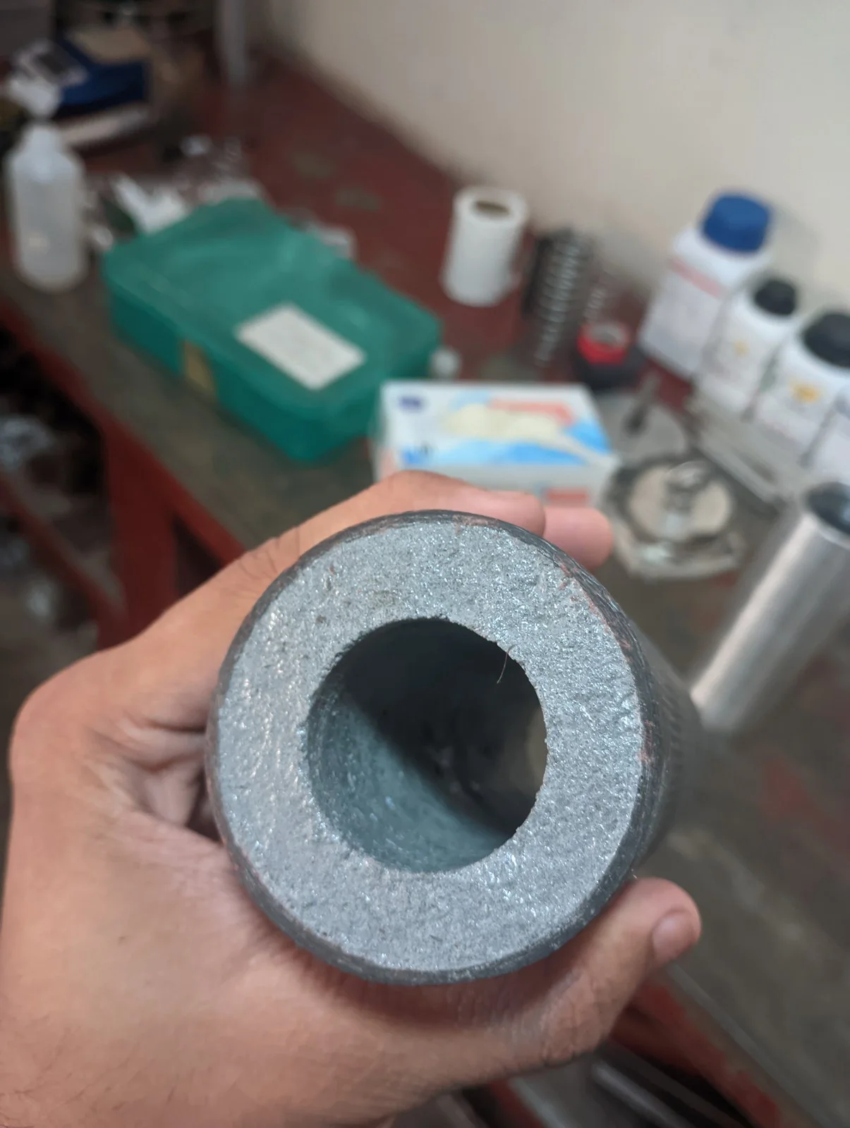
One grain, 150 mm long, cast in an oven straight into a carbon-fibre liner round a coring rod. The liner is the casting mould and then the heat shield for the casing. To try another formulation, a new lined grain goes into the same hardware.
- Grain
- 150 mm long
- Liner
- Carbon fibre
- Baseline
- KNSB · 65 : 35
Casing
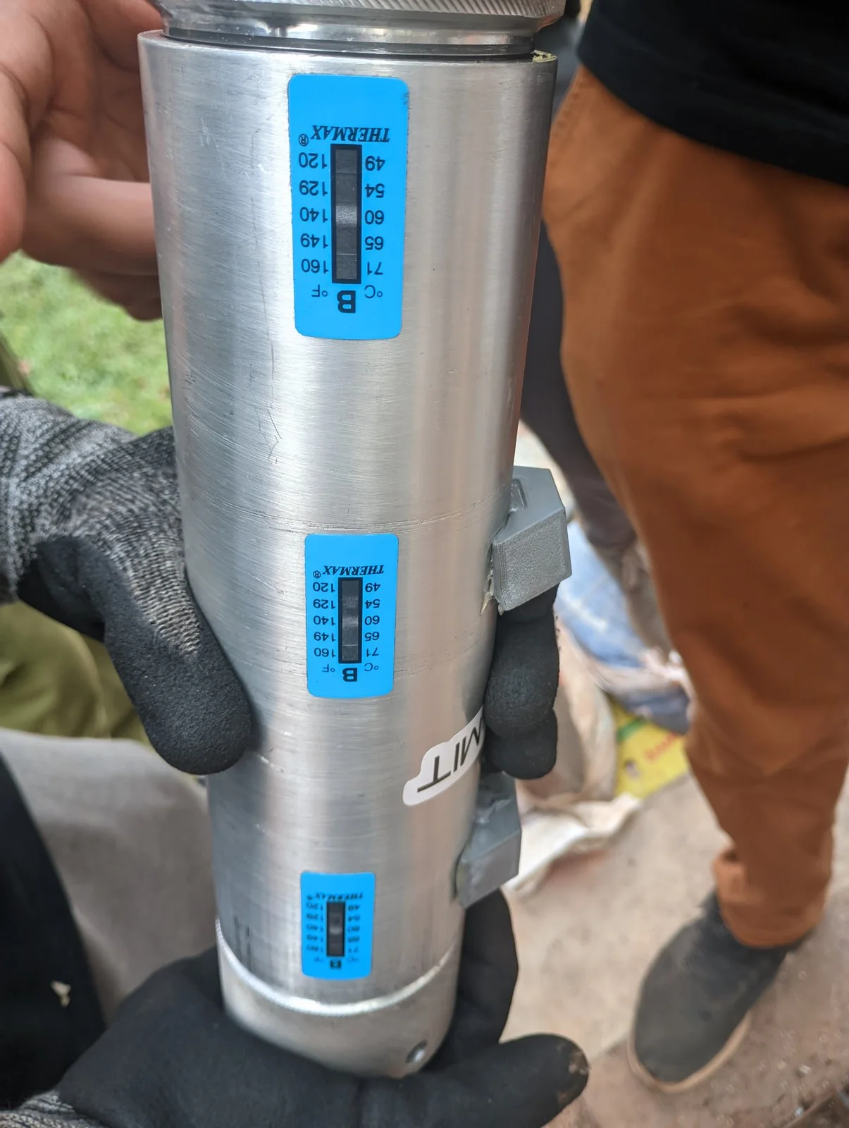
A 220 mm tube of aluminium, sized by the ASME pressure-vessel code. By calculation it bursts at 18.98 MPa, and the propellants were expected to reach 5 MPa at most. Before the firing it held water at 1.5 times its maximum expected operating pressure.
- Material
- Aluminium
- Size
- Ø73 × 220 mm
- Wall
- 5.2 mm
Nozzle
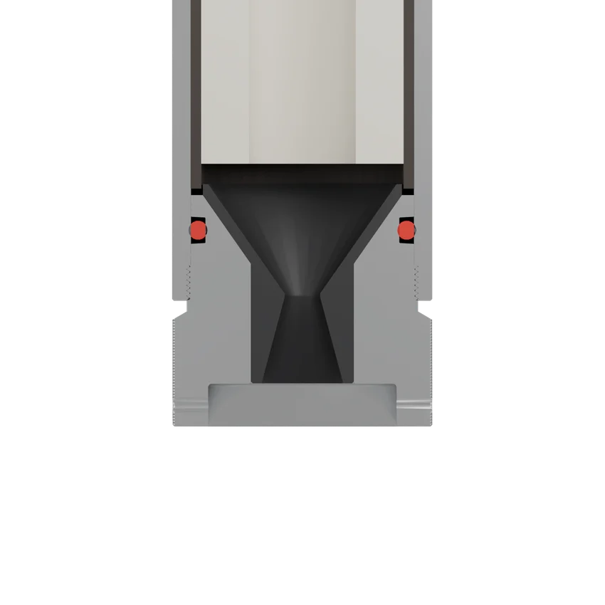
The nozzle is a separate stainless steel insert. A second knurled closure, the retainer, threads into the aft end of the casing and holds it in, sealed by a silicone O-ring.
- Insert
- Stainless steel
- Seal
- Silicone O-ring
- Retainer
- Threads into casing
- Forward closure. A knurled aluminium closure that threads straight into the casing, so the motor can be taken apart for the next propellant. A port through it takes the chamber pressure transducer, and a carbon-fibre disc shields its face from the flame.
- Propellant grain. One grain, 150 mm long, cast in an oven straight into a carbon-fibre liner round a coring rod. The liner is the casting mould and then the heat shield for the casing. To try another formulation, a new lined grain goes into the same hardware.
- Casing. A 220 mm tube of aluminium, sized by the ASME pressure-vessel code. By calculation it bursts at 18.98 MPa, and the propellants were expected to reach 5 MPa at most. Before the firing it held water at 1.5 times its maximum expected operating pressure.
- Nozzle. The nozzle is a separate stainless steel insert. A second knurled closure, the retainer, threads into the aft end of the casing and holds it in, sealed by a silicone O-ring.
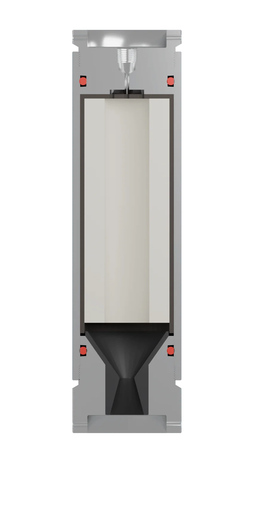
Forward closure
A knurled aluminium closure that threads straight into the casing, so the motor can be taken apart for the next propellant. A port through it takes the chamber pressure transducer, and a carbon-fibre disc shields its face from the flame.
Propellant grain
One grain, 150 mm long, cast in an oven straight into a carbon-fibre liner round a coring rod. The liner is the casting mould and then the heat shield for the casing. To try another formulation, a new lined grain goes into the same hardware.
Casing
A 220 mm tube of aluminium, sized by the ASME pressure-vessel code. By calculation it bursts at 18.98 MPa, and the propellants were expected to reach 5 MPa at most. Before the firing it held water at 1.5 times its maximum expected operating pressure.
Nozzle
The nozzle is a separate stainless steel insert. A second knurled closure, the retainer, threads into the aft end of the casing and holds it in, sealed by a silicone O-ring.
Static fire
The problem
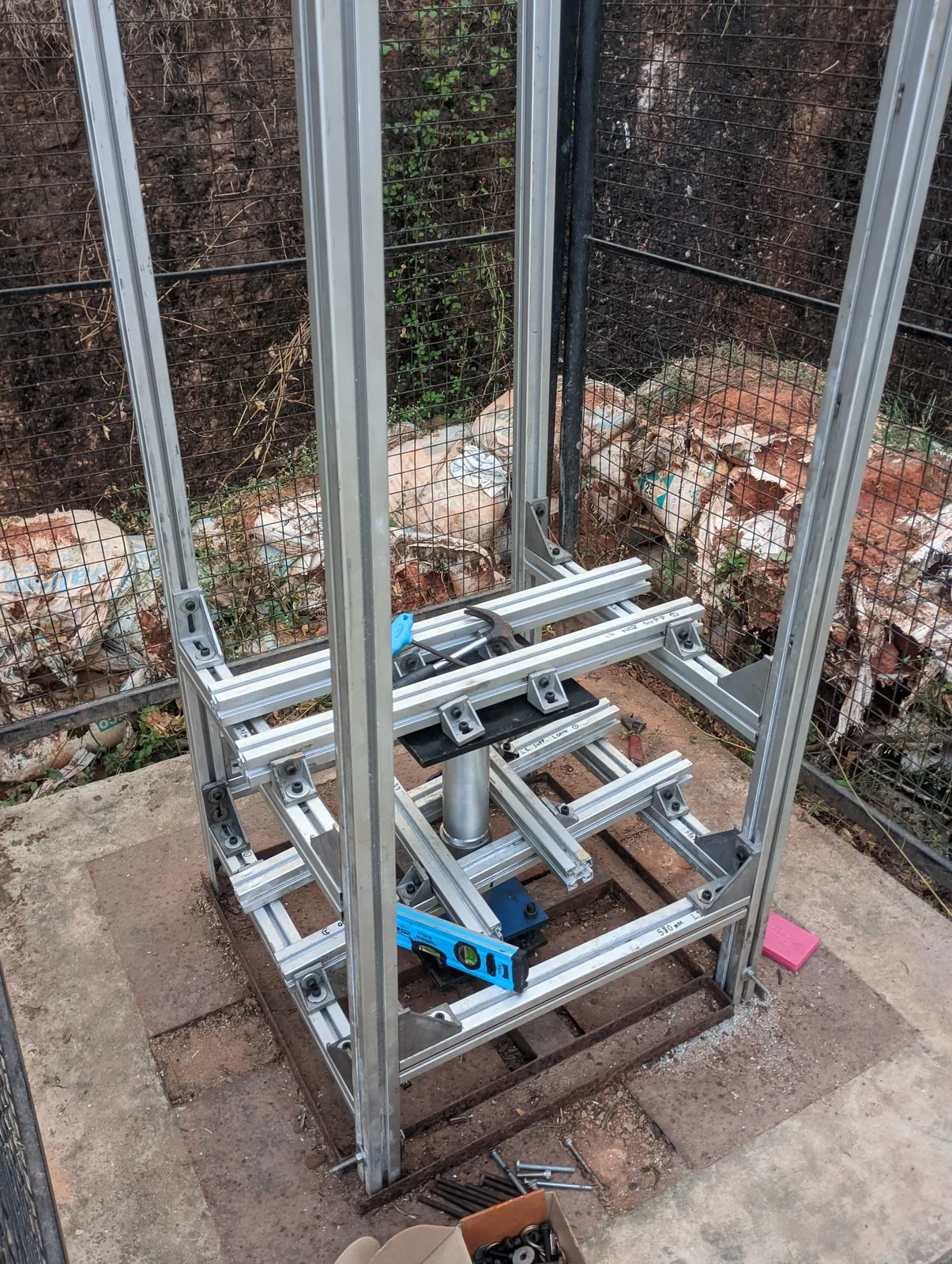
Every motor the team had fired used KNSB. We wanted to try nitrate propellants that calculate well above it, on one reusable motor instead of a new motor for each.
Design
A 220 mm aluminium tube with a threaded, knurled closure at each end. To change propellant, unscrew both, clean the parts and load a new grain.
- Ø73 × 220 mm · 5.2 mm wall
- Silicone O-ring seals
- Burst 18.98 MPa · design 12.65 MPa
- MEOP 8.44 MPa
- Safety factor 2.53 at 5 MPa
- Thread engagement 10 mm
- Port for a pressure transducer
- Pressure port
- Forward closure
- O-ring
- Carbon headliner
- Cast grain
- Carbon-fibre liner
- Aluminium casing, 5.2 mm wall
- Nozzle insert
- O-ring
- Nozzle retainer
Casting
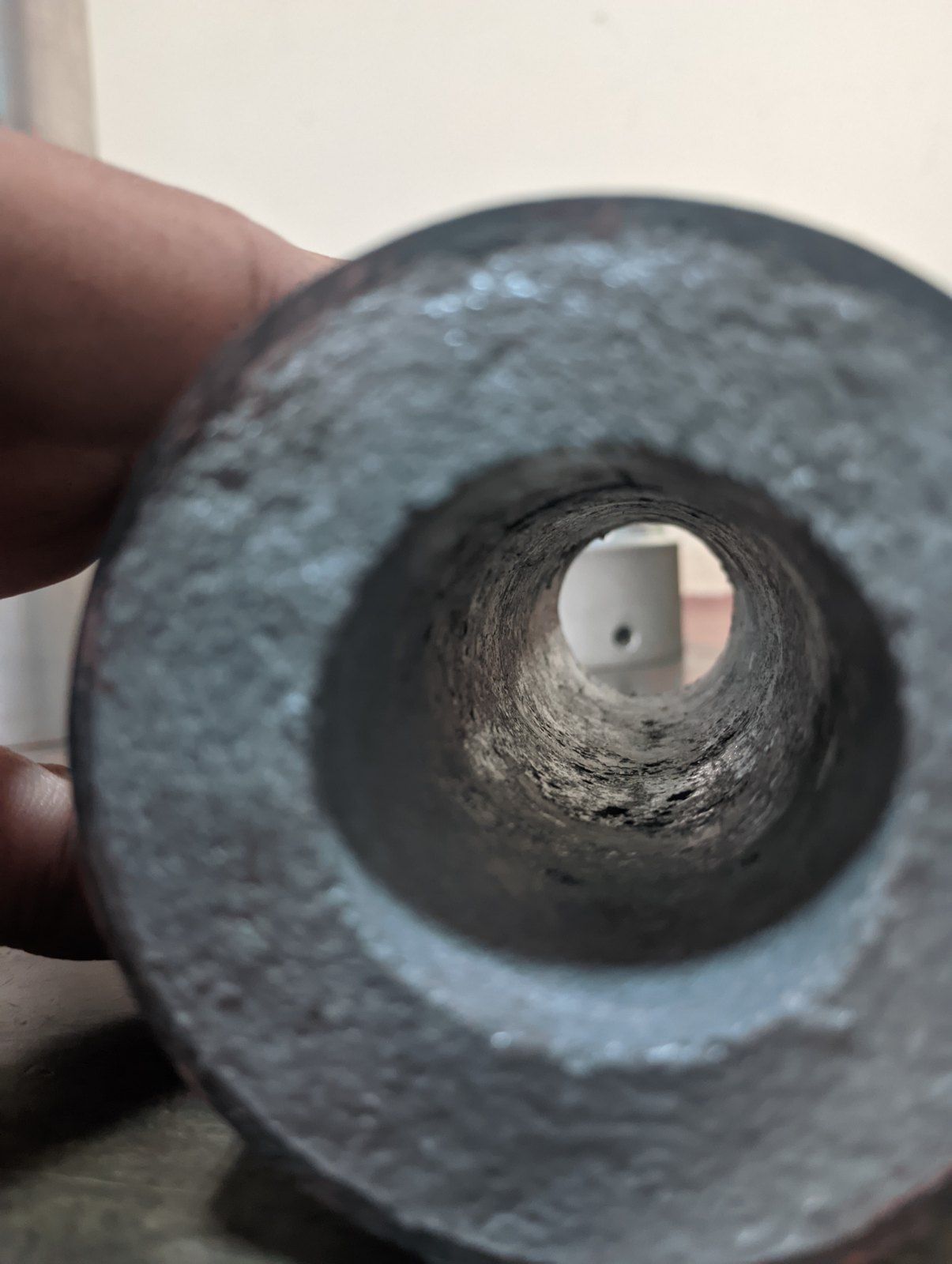
Lots of casting tests were done with both formulations to ensure safe, good-quality grains. Grains were cast in an oven at 120 °C for 30 to 35 minutes, straight into carbon-fibre liners, then centred, compacted and checked for voids.
Testing
Proof test
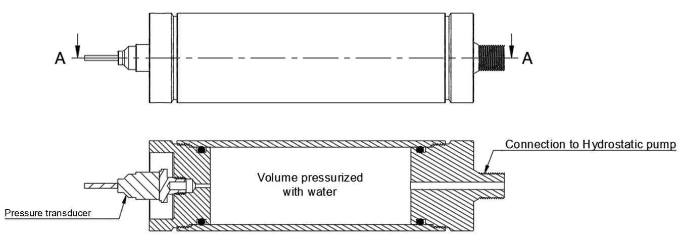
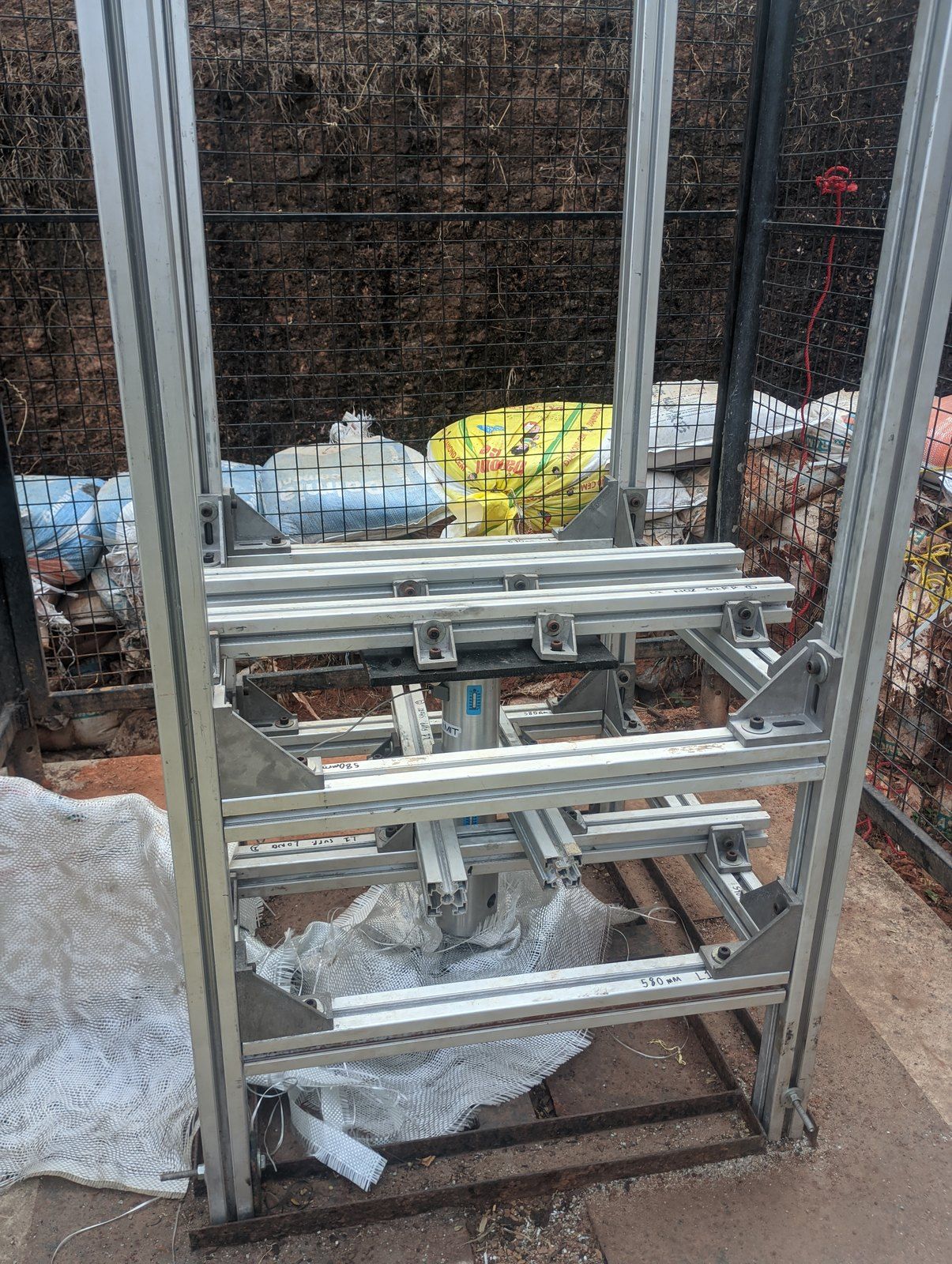
Water at 1.5 × MEOP
- Both closures sealed
- Checked for leaks and deformation
Static fire
Smooth burn
- Formula 1 propellant
- Slow ignition
- No structural failure
Gallery
Next
Solar Sail Deployment Mechanism
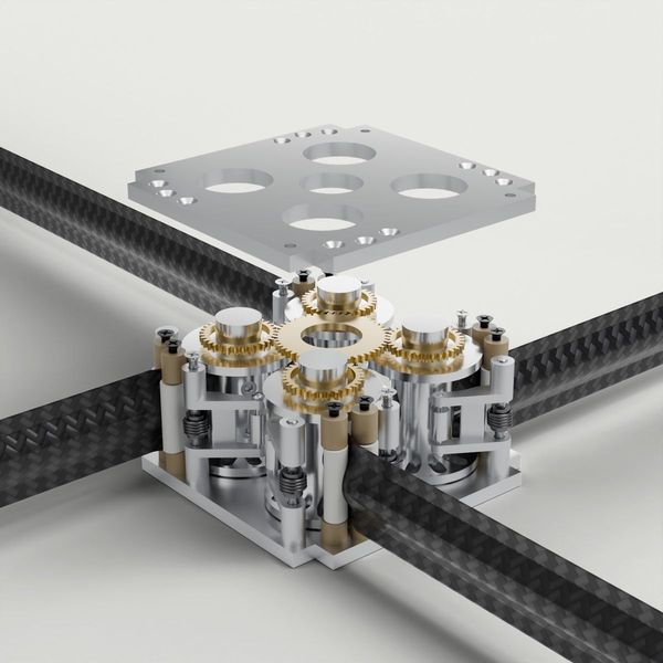
Motor-driven boom deployer for a 16 m² CubeSat sail, placed third in a MAHE design challenge.
RoleConcept Design2025